
Udacity Self-Driving Car System Integration Project
Final project for the Udacity Self-Driving Car Nanodegree: Programming a Real Self-Driving Car. Using ROS to integrate the planning, traffic light detection and vehicle controls.
Programming a Real Self-Driving Car.
This is the project repo for the final project of the Udacity Self-Driving Car Nanodegree.
Team: Experienced Drivers
| Name | |
|---|---|
| Xiang Jiang (Team Lead) | jx.for.jiangxiang@gmail.com |
| Ahmed Khatib | ackhatib@gmail.com |
| William Wu | willywu2001@hotmail.com |
| Haribalan Raghupathy | haribalan.r@gmail.com |
| Ilkka Huopaniemi | ilkka.huopaniemi@gmail.com |
Implementation
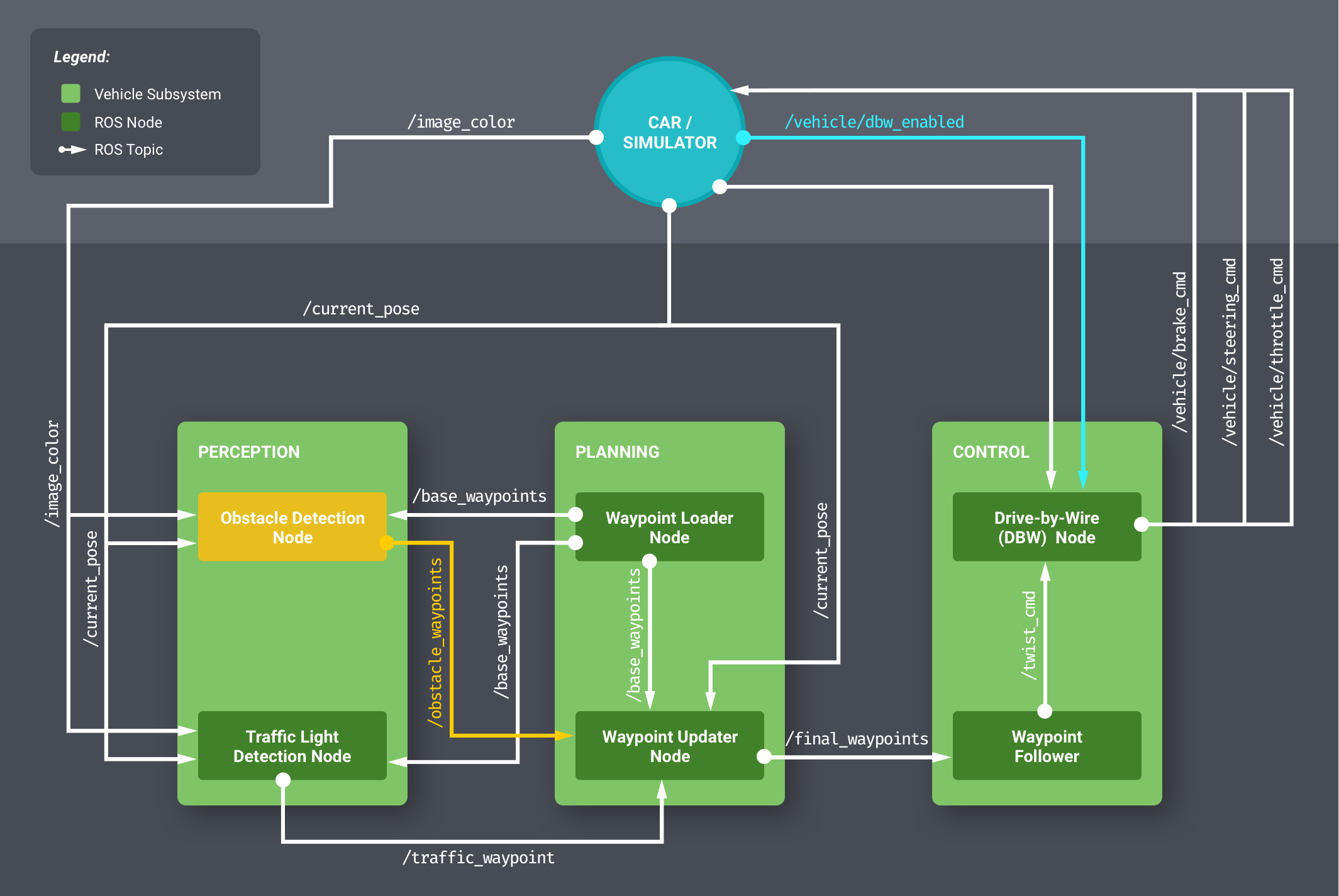
The starter repo provided the skeleton of the architecture in Figure 1 with all of the ROS nodes stubbed out. There are three ROS nodes in this diagram that we implemented.
- Waypoint Updater Node
- DBW Node
- Traffic Light Detection Node
Waypoint updater
The waypoint updater node publishes waypoints starting from the car's current position up to some threshold in front of the car. These waypoints are published to the final_waypoints topic.
The waypoint updater node subscribes to the following topics:
/current_poseemits current position of the car./base_waypointsemits planned route of the car as an array of waypoints./current_velocityemits current velocity of the car./traffic_waypointsemits information about the state of the traffic light ahead
Pose Callback
This is the callback function that receives the current position of the car.
Whenever it receives a new position of the ego-car, it searches for the waypoints closest to the car.
If the car's position has changed since the last update, the node shifts the window of active waypoints ahead of the car and remove those behind the car.
If the car's position hasn't changed "much" between updates, we don't publish updated waypoints to avoid sending duplicate data.
This has an exception where if the car is trying to resuming from a stopped state, the node publishes updated waypoints even when our position hasn't changed "much" this is to prevent the car from stalling.
Traffic Light Callback
This is the callback function that receives the closest red light waypints.
If the value is -1 meaning no red light nearby, we will publish the received /base_waypoints. If there is a visible red light ahead, the car needs stop at the defined stop line and resuming when the light turns green.
We achieve both stopping and resuming by setting the velocity property of the waypoints in front of the car.
For stopping we linearly decrease the speed of each waypoint using the car's current position and the light's top line to determine the rate of decrease. To make sure it does not overshoot we set extra_brake_wps so that if the car overshoots by accident it will still try to stop and not continue through the intersection.
For resuming we gradually bring the car back to the pre-configured target velocity set by the launch file. We again linearly increase the waypoint velocity value from 0 to target velocity.
Some flags like self.stopping and self.resuming are present to track the current state of the car.
Calculating distance between waypoints
To decelerate/accelerate the car, we need to calculate a linear relationship between the start/end waypoints and speed. First we calculate distance between waypoints:
def distance(waypoints, wp1, wp2):
    dist = 0
    dl = lambda a, b: math.sqrt((a.x-b.x)**2 + (a.y-b.y)**2 + (a.z-b.z)**2)
    for i in range(wp1, wp2+1):
        dist += dl(waypoints[wp1].pose.pose.position, waypoints[i].pose.pose.position)
        wp1 = i
    return dist
Then we can use this to calculate the speed of each waypoint leading up to a stop or target velocity.
def decelerate_waypoints(waypoints, closest_idx):
    newWps = []
    for i,wp in enumerate(waypoints):
        p = Waypoint()
        p.pose = wp.pose

        stop_idx = max(stopline_wp_idx - closest_idx - 2, 0)
        dist = distance(waypoints,i,stop_idx)
        vel = math.sqrt(2 * MAX_DECEL * dist)
        if vel < 1.0:
            vel = 0.0

        p.twist.twist.linear.x = min(vel, wp.twist.twist.linear.x)
        newWps.append(p)
    return newWps
DBW (Drive-By-Wire)
We update dbw_node.py and twist_controller.py. Drive-by-wire (DBW) node takes as input the target twist and publishes the driving commands: throttle, brake and steer.
The DBW node subscribes to the following topics:
/vehicle/dbw_enabledwhether DBW is enabled or disabled during manual override/current_velocitycurrent velocity/twist_cmdtarget twist which includes linear and angular velocity
The DBW node publishes to:
/vehicle/steering_cmd/vehicle/throttle_cmd/vehicle/brake_cmd
In twist_controller.py, we create 3 controllers:
accel_controlleris a PID controller to control the target acceleration.lowpass_filteris a Low Pass Filter to smooth out and reduce the noise of the target acceleration calculated by theaccel_controller.yaw_controlleris a Yaw Controller to calculate the target steering based on target and current linear and angular velocity.throttle_controlleris another PID controller that takes acceleration output from thelowpass_filterand calculates the actual throttle command.
We reset the throttle_controller when manual override is active to prevent errors from building up in the controller.
If acceleration is negative, we calculate brake based on vehicle status specified by the input controller.
Proportional-Integral-Derivative (PID) controller doesn't get any simpler than this:
class PIDController:

    def __init__(self, kp, ki, kd, mn=float('-inf'), mx=float('inf')):
        self.kp = kp
        self.ki = ki
        self.kd = kd
        self.min = mn
        self.max = mx
        self.int_val = 0.0
        self.last_error = 0.0

    def step(self, error, sample_time):
        i = self.int_val + error * sample_time;
        d = (error - self.last_error) / sample_time;
        self.last_error = error

        val = self.kp * error + self.ki * i + self.kd * d;

        if val > self.max:
            val = self.max
        elif val < self.min:
            val = self.min
        else:
            self.int_val = integral

        return val
Traffic Light Detection
We updated tl_detector.py and added cv_method.py
Resubmission notes:
cv_method.py did not work for Carla driving. Reason being the filtering if too dependent on the lighting condition and would change a lot due to weather.
We have not switched back to our original NN method. This will be described in later section and code in carla.py
Traffic Light Detector
The traffic light detection node is responsible for recognizing traffic lights and determining their state eg: red, yellow or green.
The traffic light detection node subscribes to the following topics:
/current posecurrent position of the car/base_waypointsplanned route/vehicle/traffic_lightspositions of all traffic lights/image_colorcolor of the current light in front of the car
Basically, it detects if there is a visible red light ahead or not. It will publish its result to /traffic_waypoint.
Much of the work was dedicated to the process_traffic_lights function.
Here we first computed the position of all the lights and stopping line before it.
Then for each updated current position, we check if there is an upcoming traffic light within 60 waypoints distance. If so we ask the classifier what color. If it is RED, we pass it through STATE_COUNT_THRESHOLD and publish it to the waypoint updater node through /traffic_waypoint topic.
The traffic light classifier takes an image as input and returns if there is a red light present. We have been trying out both Neural Network based or classical vision based algorithms. We have decided to use the classical vision method. The reason is due to the fact that we have been using the VM provided by the course and it does not have enough computation resources to run NN in tensor flow on real-time.
We have working NN that is able to detect the light correctly, but by the time it is done, the car has already driven past the traffic light.
This leads to our classical vision method using OpenCV functions.
It is implemented in cv_method.py
Pure OpenCV Approach
The idea behind our algorithm is to detect a red filled circle within an image.
We use cv2.HoughCircles to achieve it, however, there are more things to consider here. The source of this method is from this blog post Reference.
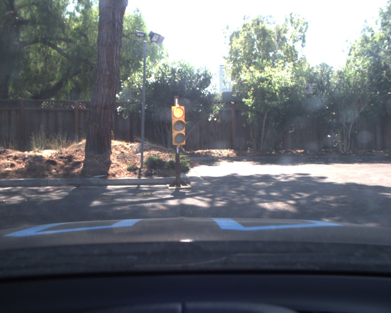
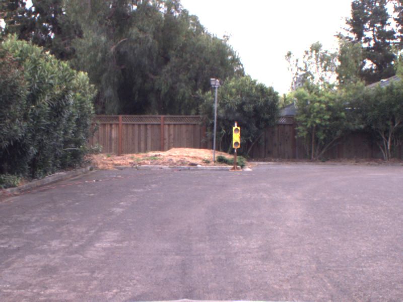
It is able to detect a red colored circle. The algorithm described in the blog post is able to detect a red circle in the simulator. However, it is not the case for ROSBAG real-life image.
Color is different in real life due to lighting.
The color threshold set for the simulator is almost perfect red. While in ROSBAG it is very bright and closer to orange.
Solution: we have added separate cv2.inRange function to cater both the real life and simulator.
HoughCircles does not care if a circle is filled or not.
HoughCirlces are circles detection but we need the circle to be filled for red light detection. This leads to a lot of false positive as well.
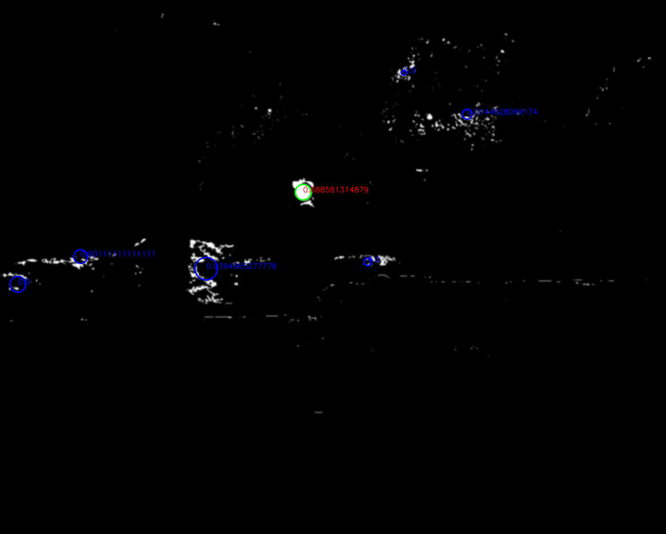
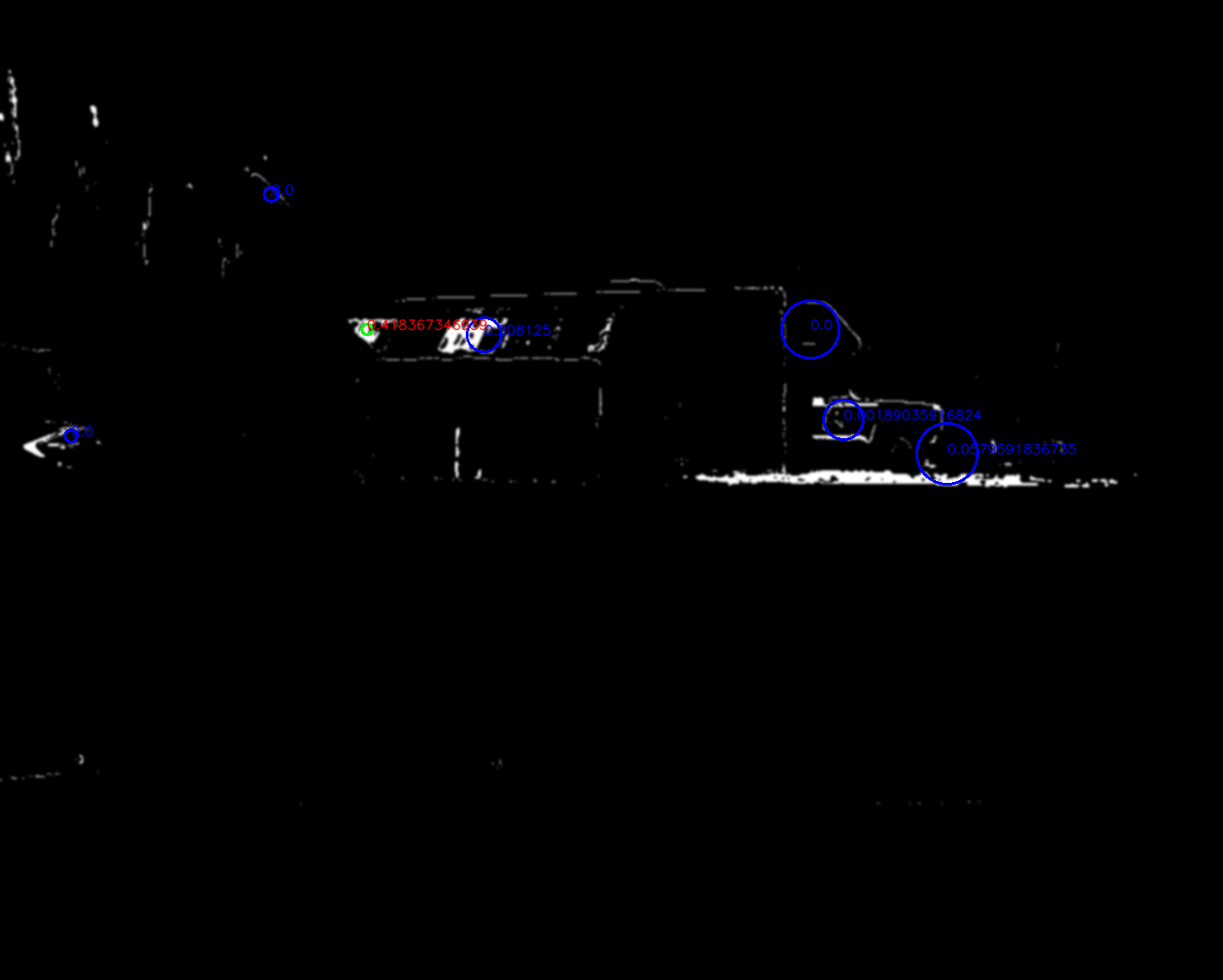
Solution: After HoughCircles returns a list of circles, I applied a cv2.countNonZero to see how filled it is, if it is below a certain value, it is not counted as a detected light. Notice in the image below, only the green circle is the circle that is filled and counted as a red light.
False Positives
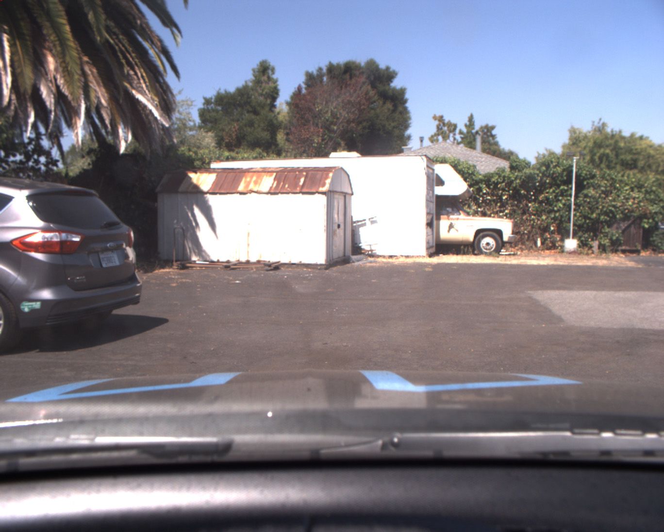
The environment, due to the sunlight, has a lot of bright red spots that have exactly the same color as the traffic light. This results in a lot of false positives.
Solution: STATE_CHANGE_THRESHOLD is increased to 5 so that we can allow more false positives. Also, we increase minimum distance between two circles in HoughCircles function so that false positives that clustered together can be eliminated. Notice below some false positive even after the filled ratio threshold will still be unavoidable.
Stopping Too Late
Another problem we have seen is in the simulator, it the traffic light changes to red right before we pass the stop line, we might not be able to stop the car on time.
Solution: Deliberately increase the threshold to detect yellow color as well. So the car can be made aware it is going to be RED soon and slow down in advance.
As a result: in our project loginfo, we will output only two scenarios when we publish upcoming red light after state count thresholding. They are:
[RED or YELLOW] vs [GREEN or UNKNOWN] as shown below:
[INFO] [1522422382.484703]: GREEN or UNKNOWN
[INFO] [1522422383.484754]: GREEN or UNKNOWN
[INFO] [1522422383.484896]: GREEN or UNKNOWN
[INFO] [1522422385.484902]: RED or YELLOW
[INFO] [1522422385.484941]: Breaking distance to light: 53.1394
[INFO] [1522422385.484959]: RED or YELLOW
[INFO] [1522422385.484967]: RED or YELLOW
[INFO] [1522422386.485123]: RED or YELLOW
Carla
Due to hardware constraints on our end, we did not use a neural network classifier initially. But the pure CV approach was proving insufficient when running on the actual car. We decided to switch back to using a neural network classifier and optimize our usage.
We used a pre-trained model from tensorflow detection model zoo.
We picked ssd_mobilenet_v1_coco since it is the fastest.
This model is trained w.r.t. COCO dataset where there traffic_light is a class. So by passing an image into the network, boxes are returned to indicate object detected and type of the object.
It is a single-shot detector (SSD) using mobilenet architecture.
Inputs are 300x300 for the network.
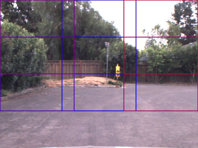
So we provided 6 regions of interest with size 300x300, assuming our images are 600x800.
We loop over the 6 regions of interest and feed it into the classifier.
If a traffic light is detected, we will stop searching to save time.
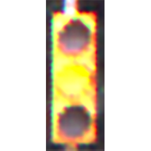
Once a traffic light has been boxed. We will convert the cropped image to HSV like the pure CV approach used previously.
Looking at the V color value, we filter the very bright pixels and get an average height of it.
We also filter out the very dark pixels and get an average height of it.
If the light is on top and darkness is at the bottom, then it is a red light.
brightness = cv2.cvtColor(traffic_light, cv2.COLOR_BGR2HSV)[:,:,-1]
light_h, _ = np.where(brightness >= (brightness.max() - 5))
dark_h, _ = np.where(brightness <= (brightness.max() - 50))
total_h = traffic_light.shape[0]
combined_h = (light_h.mean() + (total_h - dark_h.mean())) / 2
light_ratio = combined_h / total_h

if light_ratio < 0.53: # A larger value includes more YELLOW
    return TrafficLight.RED
if light_ratio > 0.60:
    return TrafficLight.GREEN
return TrafficLight.YELLOW
This method assumes the traffic light setup is vertical and RED always on top.
We try to treat YELLOW lights as RED to be cautious and attempt to slow down at yellow lights.
Summary
With the above implementation, we successfully ran our algorithm in both simulator and ROSBAG files. Running on the actual car was challenging and there were some cases when red or green lights were missed, but overall, the project was fun, challenging and we all learned a lot about each component as well as putting everything together in a functioning system.
Check out the GitHub repo for instructions on running the simulation.